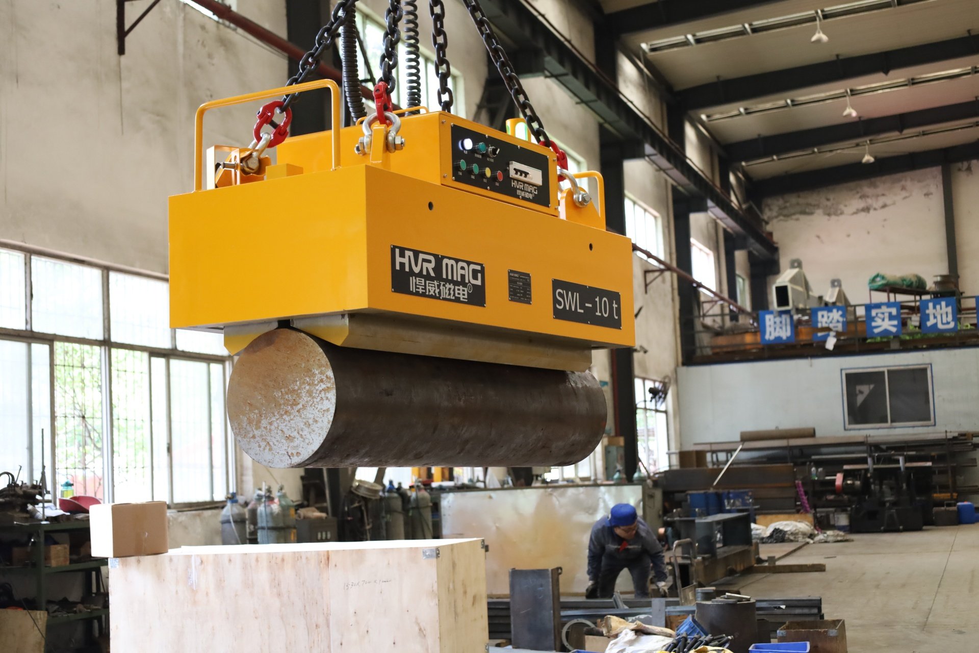


I often see a risky mistake in magnet selection. A buyer asks for ton capacity first. The real lifting condition may already reduce holding force.
Air gap affects magnet selection because it reduces effective magnetic holding force under real site conditions.1 I must check rust, paint, scale, oil, roughness, flatness, plate thickness, contact area, and lifting method before I trust any rated capacity.
I never treat air gap as a small lab term. I treat it as a site condition. It decides if an electro-permanent lifting magnet has enough safety margin after it touches real steel. I have seen many projects change after I ask for plate photos, flatness details, and surface condition. A catalog value can start the discussion. It cannot finish the selection. If I ignore air gap, I may choose a magnet that looks strong on paper but feels weak in daily production.
What Do I Mean by Air Gap in Real Steel Plate Lifting?
I often see air gap being treated too simply. People imagine a visible space. The bigger problem is the invisible loss of real contact.
Air gap means any condition that keeps the magnet pole from making full, clean, flat contact with the steel. I include rust, paint, mill scale, oil, dust, surface roughness, bending, and poor flatness2.

I use a practical meaning of air gap when I select an electro-permanent lifting magnet. I do not only look for a visible gap. I also look for anything that weakens the magnetic circuit between the magnet and the workpiece. A painted plate may look flat. It can still reduce holding force.3 A rusty plate may seem heavy and safe. It can still reduce contact quality. A long plate may touch the magnet at some poles and miss contact at other poles. That is also an air gap problem.
Common sources of air gap I check
| Site condition | What I check | Why I care |
|---|---|---|
| Rust | Loose rust or heavy oxidation | It reduces clean metal contact |
| Paint | Paint thickness and hardness | It creates distance from steel |
| Mill scale | Scale layer and loose flakes | It changes contact stability |
| Oil | [Oil film and dirt | It lowers friction and clean contact](https://pmc.ncbi.nlm.nih.gov/articles/PMC10425402/)%%%FOOTNOTE_REF_4%%% |
| Roughness | Uneven surface marks | It reduces full pole contact |
| Warping | Plate bending or waves | It causes partial contact |
| Poor flatness | Local high and low points | It changes force distribution |
I also ask how the plate is lifted. A single plate lift is different from lifting from a stack. A thin plate is different from a thick plate. A long plate is different from a compact block. I want to know where the magnet will sit and how the plate will behave after lifting. This is why I see air gap as a real operating variable. It is not just a physics word. It is a daily production problem.
Why Is Rated Lifting Capacity Not Enough for Magnet Selection?
I often receive one short request. The request says, “I need a magnet for 5 tons.” That question is not enough for safe selection.
Rated lifting capacity is tested under defined conditions.5 Real lifting performance changes when steel grade, contact area, surface condition, flatness, thickness, and lifting method change on site.6

I use rated lifting capacity as a reference. I do not use it as the final answer. A lifting magnet rating usually depends on a specific test plate, a specific surface condition, a specific thickness, and a specific safety factor. If the customer’s plate has rust, paint, mill scale, or bending, the real holding force may be lower. If the plate is too thin, the magnetic circuit may not work as expected.7 If the contact area is too small, the pole area may not be fully used.
What I compare before I trust a rated value
| Catalog item | Real site question I ask |
|---|---|
| Rated capacity | What is the single-piece weight? |
| Test plate condition | Is the customer plate clean, rusty, painted, or scaled? |
| Test thickness | What is the actual plate thickness range? |
| Full contact | Does the plate stay flat under the magnet? |
| Center lifting | Is the load balanced during lifting? |
| Static test | Is the lift frequent, moving, rotating, or feeding a line? |
I once discussed a project where the first request only mentioned total weight. After I asked for photos, I saw heavy scale and uneven plate edges. The magnet choice changed. The beam layout also changed. The customer did not need only more nominal capacity. The customer needed better pole coverage and a safer lifting layout.
This is why I do not promise a fixed weight at a fixed air gap without test conditions. I need magnet type, steel material, plate size, contact area, and safety factor. I also need to know if the lift is horizontal, vertical, manual crane lifting, automatic line loading, or robot handling. The rated value is useful. The real workpiece data is more useful.
Can a Thicker Steel Plate Still Be Risky When Air Gap Exists?
I hear this assumption often. A thick steel plate looks safe because it has enough mass. That idea can hide a serious contact problem.
A thicker plate does not automatically make lifting safer.8 If the surface is rough, rusty, bent, painted, or poorly contacted, the magnetic circuit may still lose safety margin.

I do care about thickness. A plate must have enough thickness for the magnetic flux path. A very thin plate may be harder to lift safely, and it may deform. But thickness is only one part of the selection. A thick plate with poor flatness can still be difficult. The magnet may touch only a few high points. The rest of the pole surface may not work well. A heavy plate with heavy mill scale can also be risky, because the scale layer may not act like clean steel.
Why thickness alone is not enough
| Factor | Good sign | Risk sign |
|---|---|---|
| Espessura | Plate supports magnetic circuit | Plate is thick but uneven |
| Surface | Clean steel contact | Rust, paint, scale, oil |
| Flatness | Full pole contact | Warping or waves |
| Contact area | Pole face sits fully | Only edge or point contact |
| Lifting layout | Load stays balanced | One side drops or bends |
| Plate behavior | Plate stays stable | Plate flexes during lifting |
I also look at how large the plate is. A long steel plate may sag after lifting.9 That sag can change pole contact. A wide plate may need several magnet modules and a beam, not one central magnet. A narrow strip may need a different pole arrangement. A cut plate may have burrs or uneven surfaces. These details matter more than a simple thickness number.
I prefer to think in terms of safety margin. I ask if the magnetic circuit can still hold safely after real contact loss. I also ask if the layout can keep the load balanced. I do not see “bigger magnet” as the only answer. A larger magnet may help in some cases. It may fail if the pole does not contact the steel correctly. Magnet selection is a system decision. It includes the magnet, beam, pole layout, workpiece shape, and lifting process.
thick steel plate air gap magnet lifting describe.
Data I ask before I design the solution
| Information | Why I need it |
|---|---|
| Plate length and width | I need to design beam length and magnet positions |
| Plate thickness range | I need to check magnetic circuit performance |
| Single-piece weight | I need to check lifting force and safety margin |
| Steel material | I need to check magnetic response |
| Surface condition | I need to estimate air gap risk |
| Flatness or warping | I need to check pole contact |
| Lifting method | I need to match crane, automation, or robot handling |
| Lifting frequency | I need to consider duty cycle and operation flow |
| Pick-up style | I need to know if plates are lifted from stack or single position |
| Safety requirements | I need to match site standards and risk level |
I often explain this to customers in a simple way. I am not making the process harder. I am trying to avoid a wrong solution. If a customer says the plate is clean and flat, I may choose one layout. If photos show scale and bending, I may choose another layout. If the customer lifts thin sheets, I may recommend a different magnet style. If the customer lifts long plates, I may use several magnet modules along a beam.
The best selection starts before the drawing. It starts with honest site data. This is especially important for steel fabricators, steel service centers, shipyards, wind power factories, and heavy fabrication shops. These sites do not lift perfect lab samples. They lift real steel every day. Real steel has rust, edges, dirt, bends, and process limits. I need to design for that reality.
How Do I Turn Air Gap Risk Into a Safer Magnet Layout?
I do not only calculate holding force. I also design how the magnet contacts the steel. The layout can make or break the result.
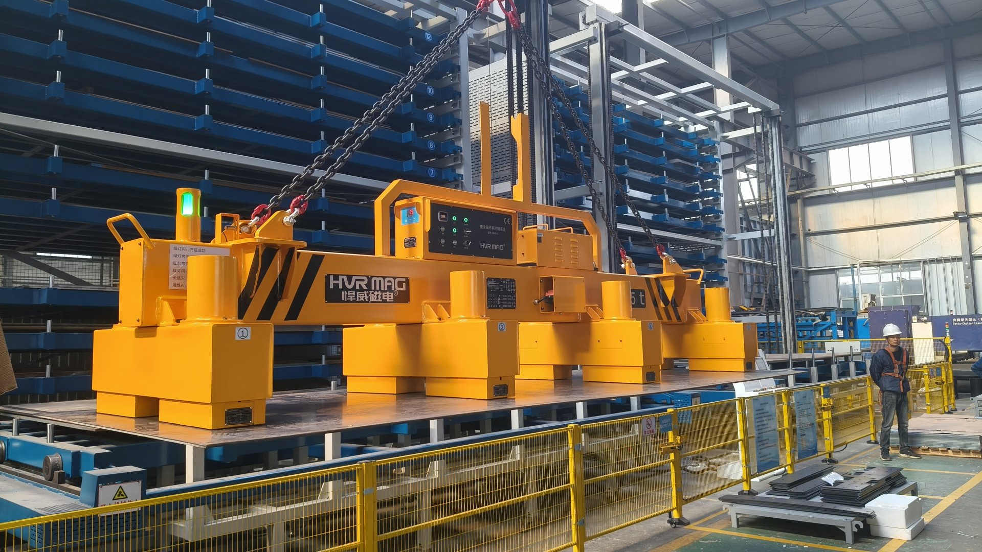
I reduce air gap risk by checking pole contact, magnet spacing, beam structure, plate bending, pickup position, and safety margin. I match the layout to the actual workpiece.

I see magnet selection as a material handling solution. The magnet module is only one part. The beam, suspension, control system, lifting points, and operator process also matter. If the plate is long, I may need a fixed beam or telescopic beam. If the plate range changes often, I may need grouped magnet control. If the plates are thin, I may need a special design to reduce deformation and avoid taking multiple sheets.10 If the lift is part of a laser cutting line, I may need fast cycle time and accurate plate release.
Practical ways I reduce air gap problems
| Design action | What it helps |
|---|---|
| [Use several magnet modules | It spreads contact across the plate](https://ntrs.nasa.gov/api/citations/19990107327/downloads/19990107327.pdf)%%%FOOTNOTE_REF_11%%% |
| Adjust magnet spacing | It supports long or flexible plates |
| Match pole design to plate size | It improves useful contact area |
| Use a proper beam | It keeps the load stable |
| Check plate flatness | It avoids hidden partial contact |
| Add safety margin | It covers normal site variation |
| Use grouped control | It fits different plate sizes |
| Review lifting route | It reduces swing and impact risk |
I do not say that a larger magnet solves every air gap problem. It may increase force, but it may not fix bad contact. If the plate is wavy, a bigger pole face may still touch only at a few points. If the lifting point is wrong, the plate may tilt. If the beam is too short, the plate may bend. If the surface has loose scale, the contact may change during lifting. I must look at the whole lifting process.
I also consider the operator’s daily use. A safe design must be easy to repeat. The operator should not need to guess where to place the magnet every time. The control system should match the work range. The beam should fit the common plate sizes. The magnet layout should allow stable pickup and release. I want the solution to work not only during testing, but also after months of production.
How Should I Discuss Air Gap With a Magnet Supplier?
I believe the supplier conversation should start with real work conditions. A simple tonnage request can lead to a weak and unsafe proposal.
I should discuss air gap with a supplier by sharing workpiece photos, plate data, surface condition, flatness, lifting process, and safety needs before asking for final capacity.

When I work on a new project, I prefer clear questions and clear answers. I ask the customer to send photos from different angles. I ask for a short video if the plate surface or bending is difficult to describe. I ask how plates are stored. I ask if the magnet will lift from a stack, a cutting table, a warehouse rack, or a production line. I ask if the plate is hot, oiled, blasted, painted, or rusty. I also ask about the crane capacity and hook height, because the complete lifting tool must fit the site.
Questions I use during early selection
| Question | What the answer changes |
|---|---|
| What is the smallest and largest plate size? | It changes beam length and magnet spacing |
| What is the thickness range? | It changes magnet type and pole design |
| What is the heaviest single plate? | It changes safety margin |
| What is the surface condition? | It changes air gap allowance |
| Is the plate flat or warped? | It changes module number and layout |
| How often is the lift done? | It changes control and operation design |
| Is automation involved? | It changes signal, release, and accuracy needs |
| What safety standard is required? | It changes design review and documentation |
I also try to avoid vague words. “Normal rust” can mean different things in different factories. “Slight bending” can also mean many things. Photos and measurements help me more than adjectives. If the customer can place a straight edge on the plate and show the gap, I can understand the flatness better. If the customer can show close photos of the surface, I can understand whether the issue is paint, scale, rust, or oil.
A good supplier should not rush to quote only from weight. I believe a good supplier should ask about contact conditions. The supplier should explain the limits of rated capacity. The supplier should also talk about safety factor, pole contact, and site testing. This does not slow down the project. It protects the project. It helps both sides avoid underperforming equipment and unsafe lifting.
Conclusão
I select lifting magnets by real contact conditions, not catalog numbers alone. Air gap changes safety margin, layout, and final lifting reliability.
"An Engineering Model of Magnetic Flux Density and ... - PMC", https://pmc.ncbi.nlm.nih.gov/articles/PMC9269161/. Magnetic-circuit analyses show that a non-magnetic air gap increases magnetic reluctance and reduces flux density at the pole-workpiece interface, providing the physical basis for lower magnetic holding force; the source does not provide a universal derating value for every lifting magnet and workpiece combination. Evidence role: mechanism; source type: paper. Supports: A source should explain that introducing a non-magnetic air gap into a magnetic circuit increases reluctance and reduces flux density and attractive force at the pole face.. Scope note: Contextual support for the mechanism, not a direct capacity calculation for the specific equipment discussed. ↩
"Magnetic lifting devices - HSE", https://www.hse.gov.uk/work-equipment-machinery/magnetic-lifting-devices.htm. Industrial lifting guidance identifies workpiece surface condition and contact quality, including coatings, scale, contamination, and flatness, as factors that can reduce magnetic lifting performance; this supports the article's checklist but does not quantify each condition's effect. Evidence role: expert_consensus; source type: institution. Supports: A standards or safety guidance source should state that surface condition, coatings, contamination, and workpiece flatness affect magnetic lifting performance.. Scope note: Contextual support for the checklist rather than a condition-by-condition force measurement. ↩
"[PDF] Magnetic method of measuring the thickness of nonmagnetic ...", https://nvlpubs.nist.gov/nistpubs/jres/20/jresv20n3p357_A1b.pdf. Studies of magnetic attraction across non-magnetic gaps show that coating thickness functions as an additional separation between the magnet and ferromagnetic workpiece, reducing the resulting pull force; the exact reduction depends on coating thickness, magnetic design, and steel properties. Evidence role: mechanism; source type: paper. Supports: A source should support that non-magnetic coatings such as paint act as an effective air gap and can reduce magnetic attraction.. Scope note: Mechanistic support, not a direct measurement for the particular paint systems in the article. ↩
"Tribological properties of high-speed steel surface with texture and ...", https://pmc.ncbi.nlm.nih.gov/articles/PMC10425402/. Tribology studies show that oil films and surface contaminants can alter friction and real contact area between steel surfaces, supporting the article's statement that oil and dirt can impair clean contact during magnetic lifting. Evidence role: mechanism; source type: paper. Supports: A tribology or handling source should support that oil films and surface contamination can change friction and contact behavior at steel interfaces.. Scope note: Mechanistic support; it does not quantify friction loss for the specific contaminants or plate surfaces described. ↩
"Citation 316036144/01001 | Occupational Safety and Health ... - OSHA", https://www.osha.gov/ords/imis/generalsearch.citation_detail?id=316036144&cit_id=01001. Below-the-hook lifting standards define rated loads and testing requirements for lifting devices, indicating that a magnet's stated capacity is tied to specified test and use conditions rather than all field conditions. Evidence role: expert_consensus; source type: institution. Supports: A standards source should confirm that below-the-hook lifting devices, including lifting magnets, are rated and tested according to specified conditions and rated-load procedures.. Scope note: Standards support the principle of defined ratings but may not list every surface and workpiece variable mentioned in the article. ↩
"Lifting Magnet Capacity Explained – Lifting365 USA", https://us.lifting365.com/pages/lifting-magnets-explained. Safety guidance for magnetic lifting notes that magnet performance depends on the load's material, thickness, surface condition, contact area, and handling circumstances, supporting the article's caution that site conditions can alter real lifting performance. Evidence role: general_support; source type: government. Supports: A government or safety guidance source should state that magnetic lifting capacity depends on load material, thickness, surface condition, contact area, and handling conditions.. Scope note: General support for the variables, not a predictive model for a specific lift. ↩
"Lifting Magnets: Permanent vs Electromagnetic - Holloway Houston", https://www.hhilifting.com/en/news/post/lifting-magnets-permanent-vs-electromagnetic-capacity-and-safety-guide?srsltid=AfmBOoo6tqKCpUV8qSqeFZUU6d9Qxg_34Q6jiJeHKnFB6n2l3KlOArqj. Magnetic-circuit research shows that the ferromagnetic workpiece forms part of the flux path and that insufficient thickness can limit flux distribution or promote saturation, reducing expected holding performance; the threshold thickness is design- and material-specific. Evidence role: mechanism; source type: paper. Supports: A source should explain the role of ferromagnetic workpiece thickness in providing a flux path and avoiding saturation or insufficient magnetic coupling.. Scope note: Mechanistic support only; actual minimum thickness must be verified for the selected magnet. ↩
"[PDF] How to choose and use lifting magnets", https://www.grainger.ca/ec/pdf/How-to-Choose-and-Use-Lifting-Magnets.pdf. Magnetic-lifting safety guidance treats plate thickness as one factor among several, including material, surface condition, contact area, and load stability, supporting the conclusion that a thicker plate is not automatically safer. Evidence role: expert_consensus; source type: government. Supports: A safety source should support that magnetic lifting safety depends on multiple factors, including surface condition, contact, and load configuration, not thickness alone.. Scope note: Supports the safety principle, not a direct comparison of all thick-plate lifting scenarios. ↩
"[PDF] 2.080 Structural Mechanics Lecture 7: Bending Response of Plates ...", https://ocw.mit.edu/courses/2-080j-structural-mechanics-fall-2013/f8fd2ad49d100766335b4e129a8a4791_MIT2_080JF13_Lecture7.pdf. Mechanics-of-materials treatments of beam and plate deflection show that members deflect under self-weight and that deflection depends strongly on span, stiffness, geometry, and support conditions, providing the structural basis for sag in long steel plates. Evidence role: mechanism; source type: education. Supports: A mechanics-of-materials source should explain that beams or plates deflect under self-weight, with deflection increasing with span and depending on stiffness and support conditions.. Scope note: Contextual mechanics support; it does not calculate sag for the specific plate dimensions in the article. ↩
"Precision Handling for Thin Steel Sheet: 3T Electro Permanent ...", https://www.hvrmagnet.com/case/precision-handling-for-thin-steel-sheet-3t-electro-permanent-lifting-magnet-233.html. Research and technical guidance on sheet-metal handling identify thin-sheet deflection and double-sheet pickup as practical risks in magnetic handling systems, supporting the need for specialized design when lifting thin plates. Evidence role: general_support; source type: research. Supports: A research or technical source should support that thin sheets can deform during handling and that magnetic handling can create double-sheet or multiple-sheet pickup concerns.. Scope note: General support for the risk; the appropriate design depends on sheet size, thickness, magnet layout, and process controls. ↩
"Deflections of a Uniformly Loaded Circular Plate With ...", https://ntrs.nasa.gov/api/citations/19990107327/downloads/19990107327.pdf. Guidance on lifting beams and multi-point lifting describes how multiple support points distribute load and can improve stability for elongated or flexible loads, supporting the use of several magnet modules to spread contact across a plate. Evidence role: general_support; source type: institution. Supports: A lifting-device or structural design source should support that multiple lifting or support points distribute load and contact over a larger area than a single point.. Scope note: Contextual design support; it does not prove that any particular module spacing is adequate. ↩